products
Instruction Manual for Belt Weighing Machine
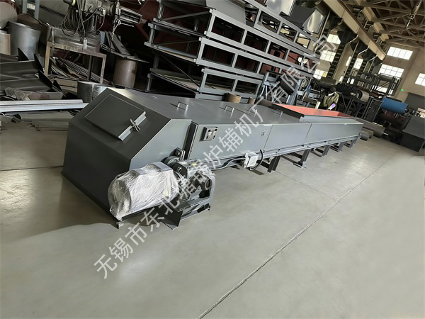
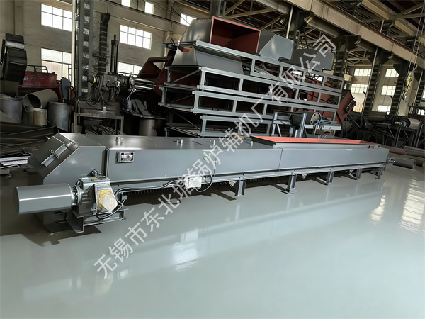
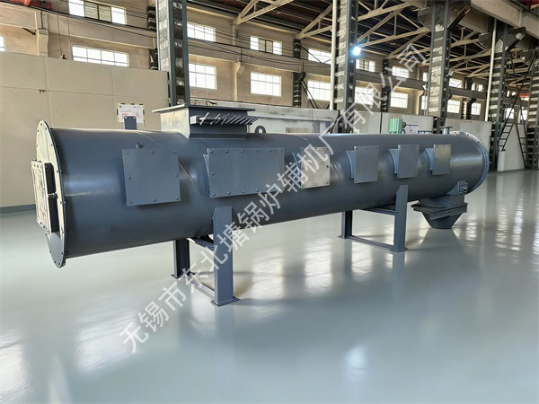
1. Equipment Overview
Belt weigher (also known as electronic belt scale) is a dynamic metering device. It continuously measures the weight and speed of materials on the belt conveyor through load cells and speed sensors installed on the belt conveyor, and automatically calculates the material flow and cumulative weight. It is widely used in batch batching and flow control in industries such as building materials, chemical industry, metallurgy, grain, and mining.
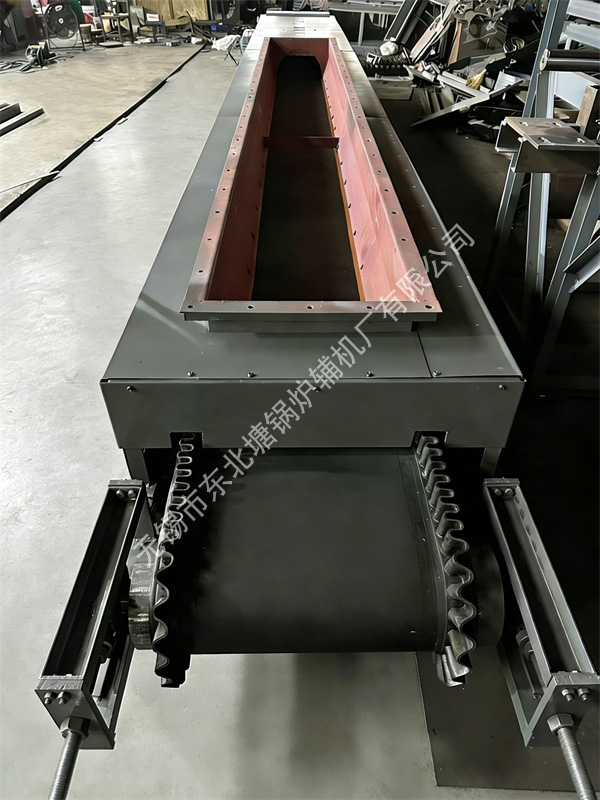
II. Core Components
1. Weighing Frame: It includes load-bearing levers, support arms, reeds, or diaphragm bearings, forming a high-precision weighing lever system.
2. Load cell: Converts gravitational signals into electrical signals (usually strain gauge type), a core measuring component.
3. Speed sensor: Installed on the driving roller or driven roller to collect the belt speed in real-time (such as rotary encoder type).
4. Integrator (controller): Receives signals, performs digital filtering, calculates flow/cumulative values, displays results, and outputs control signals.
5. Deviation and tensioning device: Ensures stable operation of the belt and guarantees metering accuracy.
3. Main Technical Parameters (General Reference)
Parameter Item Index Range
Weighing Accuracy ±0.125% ~ ±0.5% (dynamic)
Belt Speed 0.05 ~ 3.15 m/s (commonly used 0.2~2.0 m/s)
Weighing Range 1~1000 t/h (customized according to specific models)
Belt Width 300 ~ 2000 mm
Sensor Range 5~500 kg/piece (configured according to the weighing frame)
Output Signal 4-20 mA flow signal, RS-485/Modbus communication signal
Working Environment Temperature: -10℃ ~ +50℃; Humidity: ≤90%RH (no condensation)
IV. Installation and Debugging
1. Requirements for Installation Location
• Keep away from vibration sources: Avoid installing near strong vibration equipment such as crushers and vibrating screens; the recommended distance is ≥ 10 meters.
• Installation in straight sections: Must be installed in the straight section of the belt conveyor, with the lengths of the front and rear straight pipe sections being ≥ 10 times and 5 times the belt width respectively.
• Firm support: The weighing frame must be supported independently; rigid connection with the conveyor frame is strictly prohibited to avoid external force interference.
• Dust and moisture prevention: A rain cover must be added for outdoor installation, and sealing protection should be considered in environments with heavy dust.
2. Mechanical Installation Steps
1. Remove the upper and lower idlers in the installation section and install dedicated weighing idlers (usually 3-5 groups).
2. Fix the weighing frame on the independent support, ensuring the levelness is ≤ 1mm/m.
3. Install the sensor and integrator, and connect the cable (shielded wire, avoid running in the same pipe as the power line).
4. Adjust the tensioning device to make the belt tension uniform, with the initial deviation ≤ 5mm.
3. Initial Debugging (Critical)
1. No-load operation: Run continuously for 2 hours, check if the belt is deviated and if the weighing frame is free from jamming.
2. Zero calibration: In the absence of materials, perform zero tracking through the integrator to eliminate zero drift.
3. Hanging weight calibration:
◦ Hang standard weights (usually 20%, 50%, and 80% of the full range) above the belt weighing section.
◦ Set the weight of the weights, run the belt, compare the displayed value with the actual value, and correct through the range coefficient.
◦ After three-point calibration, the accuracy must meet the nominal requirements of the equipment.
V. Operation Process
1. Inspection Before Startup
• Power supply, grounding, and communication lines are connected normally.
• No foreign objects (iron blocks, large materials) are stuck on the belt.
• Check if the weighing idlers rotate flexibly and are free from material accumulation.
2. Normal Operation
1. Start the belt conveyor, and after it runs stably, start the integrator of the belt weigher.
2. The integrator enters the main interface, displaying the instantaneous flow and cumulative weight in real-time.
3. If quantitative feeding is required, set the target flow in the integrator, and the system will automatically adjust the frequency converter frequency to control the feeding amount.
3. Shutdown Operation
1. Stop feeding first, and wait until the materials on the belt are completely conveyed.
2. Stop the integrator of the belt weigher.
3. Stop the belt conveyor.
4. Clean the area around the equipment and record the cumulative amount of the current shift.
VI. Daily Maintenance
1. Daily Inspection (Each Shift)
• Observe whether the data displayed by the integrator is stable and if there are sudden jumps.
• Clean the accumulated materials and dust on the weighing idlers and frame.
• Check the belt deviation and adjust the deviation-correcting idlers in time.
2. Weekly Inspection (Every Week)
• Tighten all connecting bolts and sensor fixing screws.
• Check if the cables are worn or aged, and if the connectors are loose.
• Check the tensioning device and adjust the belt tightness.
3. Monthly/Quarterly Inspection (Every Month/Quarter)
• Perform an accuracy check with standard weights to ensure accurate measurement.
• Clean the sensor surface and check if the force is evenly applied.
• Check if the cooling fan inside the integrator is working normally.
VII. Common Faults and Troubleshooting
Fault Phenomenon Possible Causes Solutions
Large/fluctuating displayed values 1. Severe belt deviation 2. Blocked weighing idlers 3. Sensor signal interference 1. Adjust the deviation-correcting device to correct the belt 2. Clean the idler debris and add lubricating oil 3. Check the shielding wire grounding and keep away from power cables
Cumulative weight too small/large 1. Zero drift 2. Incorrect hanging weight calibration coefficient 3. Abnormal sensor force 1. Re-calibrate the zero point 2. Check the calibration parameters and re-calibrate with hanging weights 3. Check if the frame is deformed and if the sensor is damaged
No display/crash 1. Power failure 2. Damage to internal components of the integrator 1. Check the power supply voltage and fuse 2. Contact the manufacturer for repair or replace the controller
Feeding amount inconsistent with the setting 1. Incorrect frequency converter parameters 2. Fault of the speed measuring sensor 1. Check and verify the frequency converter PID control parameters 2. Check if the speed measuring wheel slips and replace the sensor
VIII. Safety Precautions
1. Strictly prohibit live maintenance: All electrical maintenance must be done with power off, and a "No Switching On" warning sign must be hung.
2. Prohibit crossing during operation: When the equipment is running, it is strictly forbidden for personnel to cross the belt or stand/walk on the weighing frame.
3. Regular cleaning: In dusty environments, clean the electrical cabinet regularly to prevent short circuits.
4. Sensor protection: It is forbidden to hit the sensor with heavy objects, and avoid lateral force during installation.
