products

1. Introduction
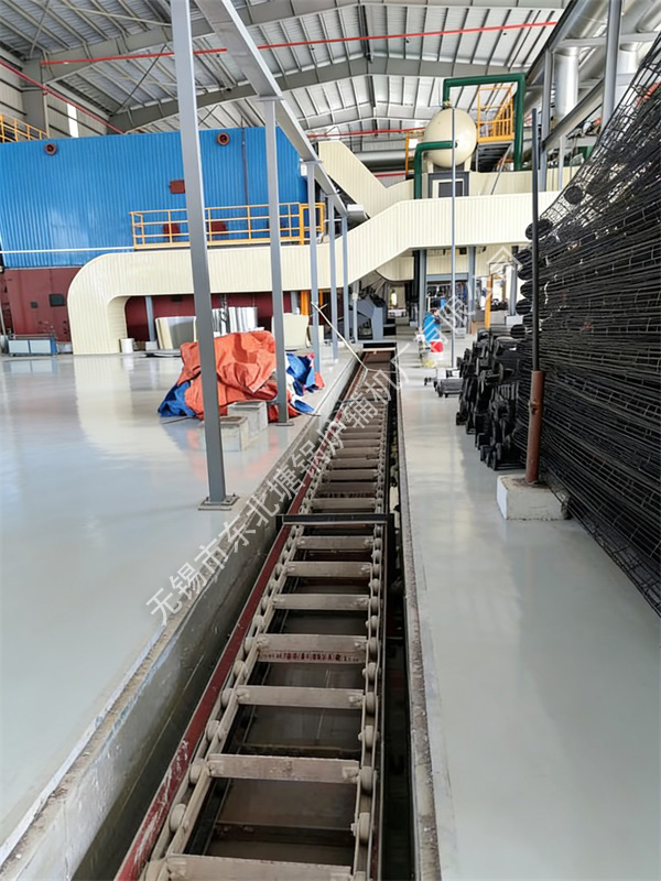
The slag extractor adopts a combined and pit-type design for joint slag discharge. The combined structure plays a significant role in reducing maintenance efforts, saving electricity, lowering noise in the workshop, and cutting down on economic expenses. To ensure the cleanliness of the workshop and the utilization rate of the workshop area, a pit-type design is adopted. Through the pit, the slag is automatically transported to the cinder yard, which has a good effect on reducing the labor intensity of stokers and minimizing air pollution.
The slag extractor is mainly characterized by its simple structure, reliable operation, and convenient maintenance and upkeep.
This slag extractor can be equipped with 2-4 boilers of various models with an evaporation capacity not exceeding 30 tons per hour. The operating length ranges from 20m to 50m, or the length can be customized according to the user's required dimensions. The model of the reducer is determined by the length of the slag extractor.
II. Main Technical Data
| 1. Reducer model | XWE=85、XWE-95 |
| 2. Speed ratio | i=1849 |
| 3. Motor power | N=1.5KW N=2.2KW |
| 4. Conveying capacity | Q=4.6T/h |
| 5. Chain speed | V=0.062m/s |
| 6. Captain | L=20m-50m |
| 7. Machine width | B=0.6m |
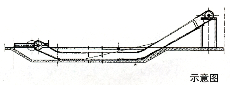
| 8. Inclination of the discharge port | ≤30° |
III. Installation Precautions
1. After the slag extractor is transported from the manufacturer to the user unit, a check on the integrity of the parts should be carried out in accordance with the general assembly drawing list to ensure that there are no missing or damaged parts.
2. The pit for installing this machine must be constructed in accordance with the pit drawing.
3. Embedded iron parts are based on civil engineering dimensions.
4. During installation, a rectangular hole shall be drilled at the position where the guide rail is aligned with the embedded iron parts. Correct the levelness and perform firm welding.
5. When installing the head, tail and guide rails, attention should be paid to the angle, perpendicularity and parallelism to prevent the chain from running to one side, which will affect the use effect.
Fourth, Conducting and Maintaining Inspections and Repairs
1. The stoker should regularly refuel and lubricate the reducer and each lubrication point according to the lubrication system diagram.
2. When using this machine, continuous cleaning should be adopted. It is strictly forbidden to clean after the coal is full, so as to avoid excessive load and damage to the machine parts.
3. After long-term use, if the guide rail is worn, the liner on the guide rail can be replaced. After the scraper is worn, round steel can be welded on the worn part to extend the service life and improve economic efficiency.
4. The tightness of the scraper chain can be adjusted to an appropriate level by adjusting the screws. It must not be too tight or too loose. When adjusting to the limit position and finding that the chain is still too loose, remove one or several sections until the tightness is appropriate.
